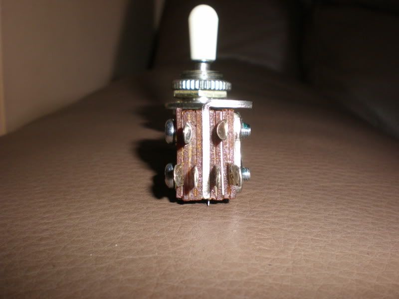
Looks like the schematic gives a better view than the wiring diagram. The neck p/up selector is picking up which pair of p/ups to pass to the standard, 3-position p/up selector. So, the neck selector is switching pairs of leads for the p/ups on one side or the other.
The schematic seems to show four leaves (arrowheads) and two commons (dots, junction points). So, I guess 6 solder points would be correct. The hot sides should be easy; two on one side, two on the other. Then, each common should go to its own respective side. I would wire up one side, and use a multimeter as a continuity tester to check my work.
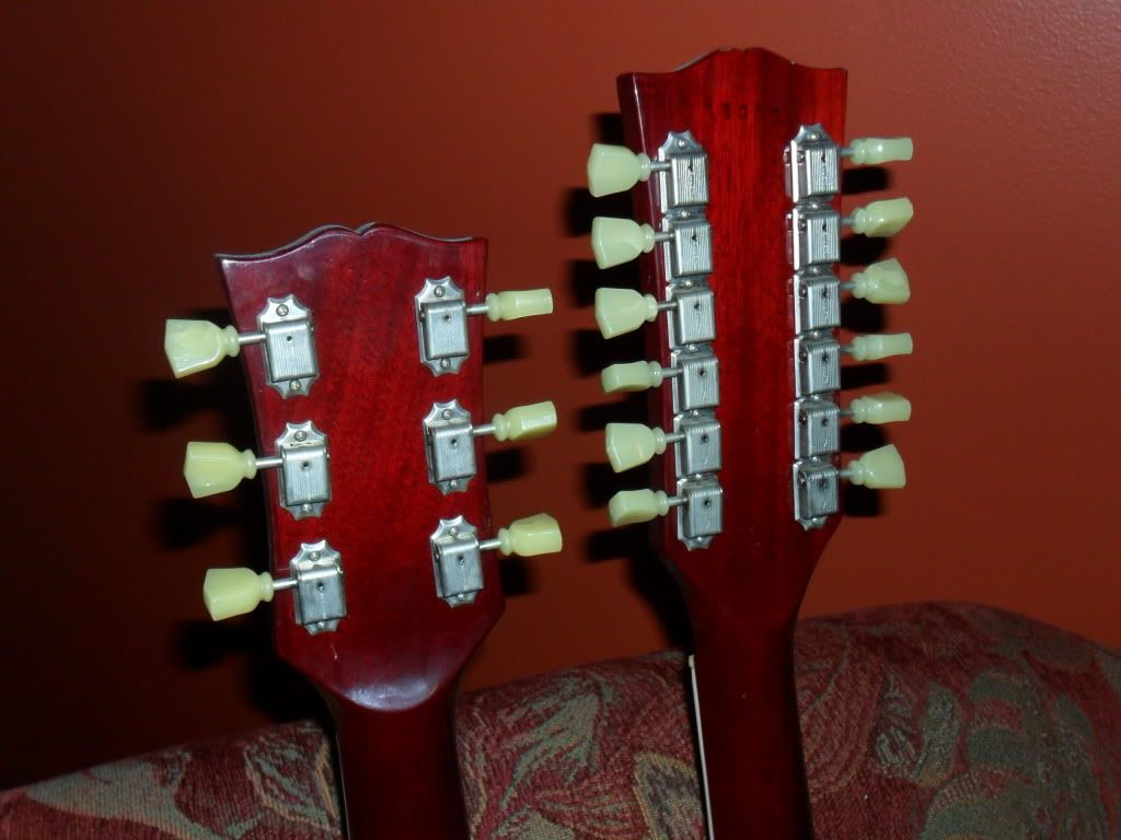
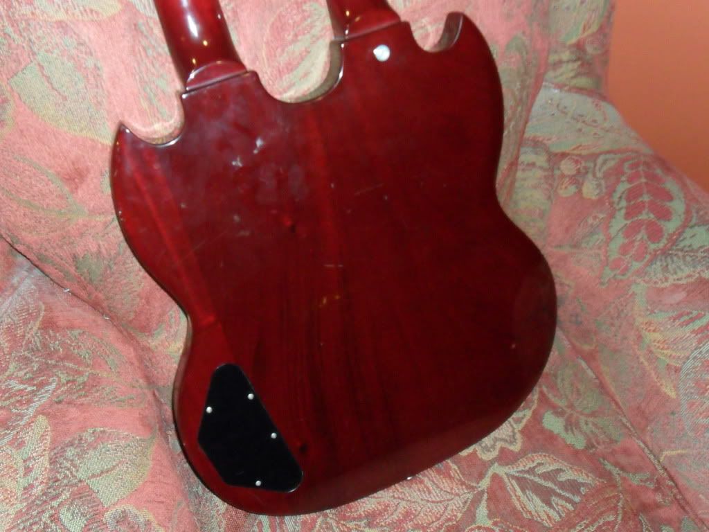
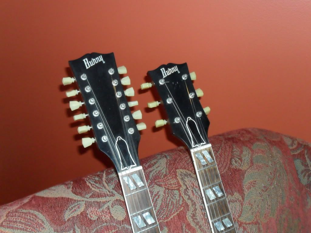
Having said that, it sure looks easy on paper, doesn't it? I rewired an old Burny FLG-120 yesterday, and it was just a mess making heads-or-tails out of what someone had done. Some people just shouldn't do their own work.


